Technical concept note
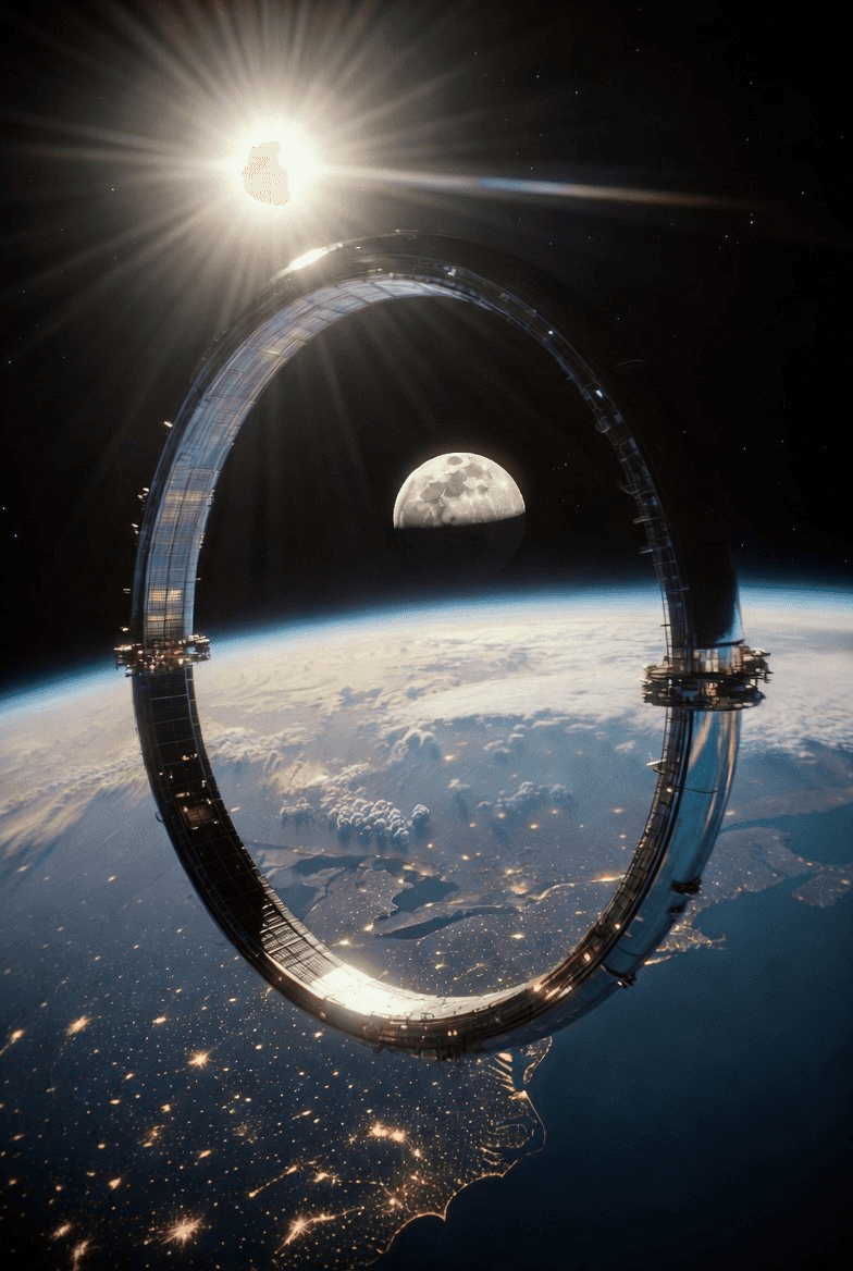
A construction roadmap for a 1.8-kilometer orbital ring habitat
A logistics-driven, operations-focused sequence for assembling a rotating toroidal space habitat using current-generation heavy-lift launch vehicles and autonomous in-space manufacturing systems.

Contents
- 00Preface
- 01Physics and habitat geometry
- 02Earth-side preparation and Starship 3 cargo
- 03The non-rotating orbital yard
- 04METRA-MULE architecture and deployment
- 05The gate-attached manufacturing platform
- 06Extrusion of the space truss frame
- 07Central hub integration and spin-up
- 08Interior construction and outfitting
- 09Steady-state operations and expansion
00Preface — purpose and scope
This document presents a logistics-driven, operations-focused construction roadmap for a 1.8-kilometer orbital ring habitat. It is written for aerospace engineers, mission planners, systems architects, and program managers who require a clear, technically grounded understanding of how such a structure can be assembled using current-generation heavy-lift launch vehicles and autonomous in-space manufacturing systems.
The scope of this note is strictly practical. It describes:
- How Starship 3 cargo constraints shape all upstream design decisions
- How dense precursor materials are transformed into ultra-light structural volume
- How a non-rotating orbital yard is established and stabilized
- How METRA-MULE robotic swarms perform unpacking, handling, and assembly
- How the manufacturing platform emerges from the delivered hardware
- How the Metatronium lattice is extruded, refined, and closed into a rigid toroidal frame
- How the central hub, spin-up systems, and interior modules are integrated
- How the completed ring transitions into long-term operations and expansion
This is not a speculative narrative. It is a structured concept note describing a buildable sequence, grounded in known launch vehicle dimensions, realistic robotic capabilities, and established principles of orbital assembly. The intent is to provide a coherent operational picture of how a large-scale artificial-gravity habitat can be constructed from first principles using modular systems, autonomous robotics, and high-density feedstock logistics.
Building a rotating toroidal space habitat — a 1.8 km “gravity wheel” — is fundamentally a logistics and systems-engineering problem. The challenge is to transform dense, compact raw material into a rigid, high-precision, artificial-gravity structure using only what can be launched through a 9 m diameter rocket fairing and expanded into approximately 11,000,000 m³ of finished lattice — the volume of roughly 4.4 Great Pyramids of Giza.
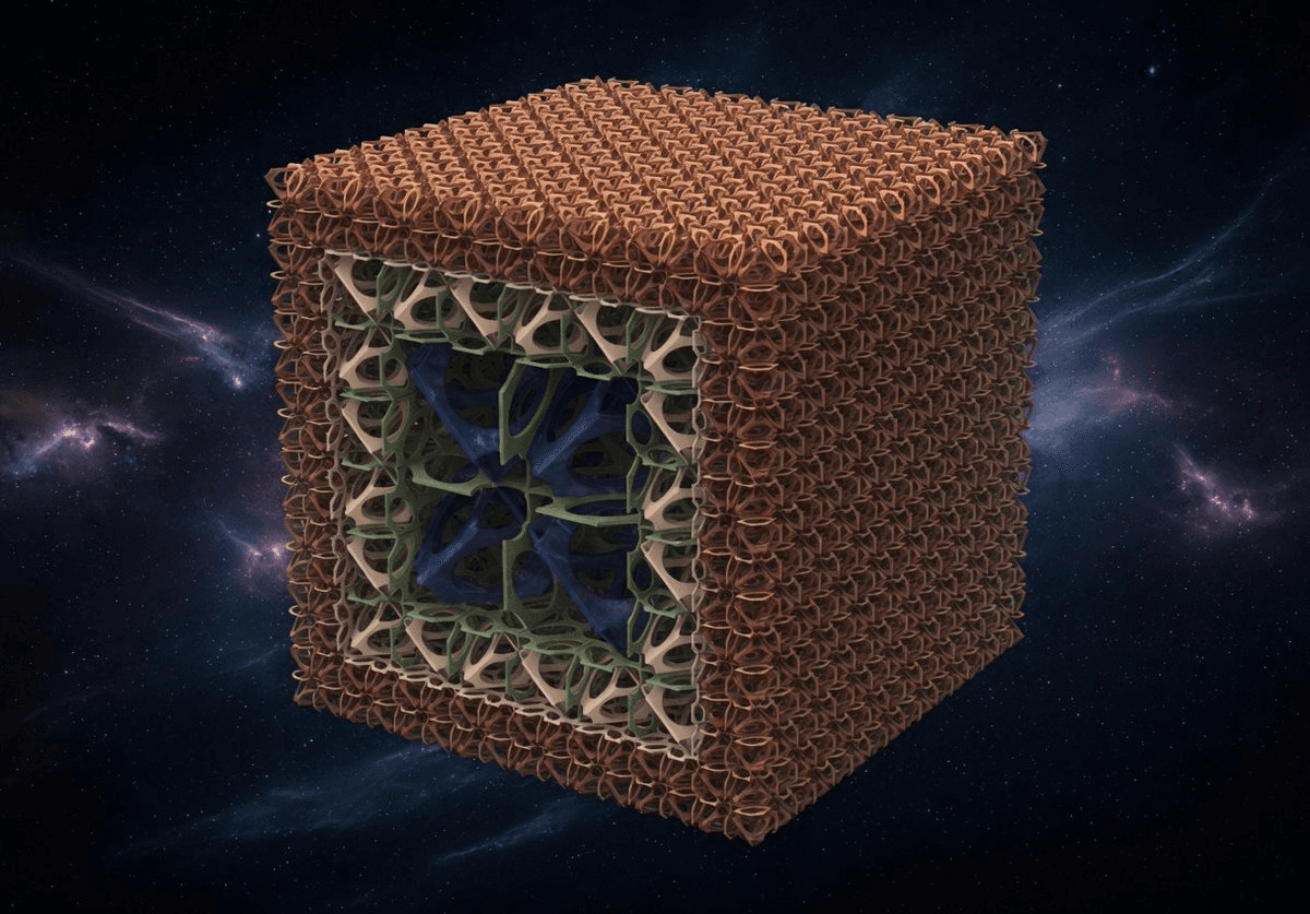
The enabling technology is Metatronium: a seven-plane lattice (three Cartesian plus four tetrahedral planes) extruded in orbit from dense precursor feedstock into an ultra-lightweight, high-strength space frame. Around this material system, we design a complete construction chain: Starship 3 cargo integration, orbital containment, robotic swarms, in-space manufacturing, and long-term operations.
This roadmap describes, in practical terms, how such a structure can be assembled.
01Physics and habitat geometry
The geometry of the ring is dictated by human physiology. To provide Earth-equivalent gravity with minimal Coriolis effects, the following parameters are fixed:
- Target spin rate
- 1 revolution per minute
- Effective gravity at living floor
- 1 g9.81 m/s²
- Radius to living floor
- 894 mfrom the central axis
- Overall ring diameter
- ~1.8 km
- Cross-section
- 160 m × 100 mradial width × axial depth
- Orientation
- Down = outwardUp = inward toward the hub
These values define the structural scale, mass distribution, and rotational dynamics. Every upstream design decision — cargo packing, lattice geometry, robotic reach, and propulsion placement — must be compatible with this envelope.
02Earth-side preparation and Starship 3 cargo
The construction process begins on the ground with a disciplined approach to how mass and volume are used inside Starship 3.
2.1 Starship 3 cargo envelope
- Outer diameter
- 9 m
- Usable internal dynamic envelope
- ~8 m diameter
- Usable height
- ~18 mextendable to ~22 m
- Workable internal volume
- ~1,000–1,100 m³
- Payload to LEO
- ~100 metric tonsreusable
2.2 Metatronium feedstock
- Transport density: ~3.21–3.5 g/cm³ (~3,200–3,500 kg/m³)
- A 100-ton load occupies ~28–31 m³ at highest density
- This forms a ~0.6 m thick plug at the base of the cargo bay
- The remaining ~900+ m³ is available for deployment systems, robotics, and structural components
2.3 Carousel deployment units
Feedstock and components are pre-organized into Carousel Deployment Units — lightweight composite magazines that hold feedstock billets and structural elements in a launch-safe configuration, designed to interface directly with orbital retrieval systems and extruders.
The key principle is simple: we launch mass, not volume. The expansion from dense feedstock to ultra-light lattice occurs entirely in orbit.
03Establishing the non-rotating orbital yard
The first Starship flights do not attempt to build a rotating structure. They establish a non-rotating construction environment analogous to the ISS, but purpose-built for large-scale assembly.
3.1 Containment net
- Deployed diameter
- ~152 m~500 ft
- Structure
- Woven grid~1 m × 1 m connection spacing
- Function
- Closed orbital yardnothing drifts away
3.2 Initial freight aggregation
Successive Starship flights deliver additional feedstock carousels, METRA-MULE robotic units, extrusion machinery and gantry components, and power, thermal, and communication modules — all released into the containment yard and safely bounded by the net until the manufacturing platform is assembled.
04METRA-MULE architecture and deployment
The METRA-MULE (Metatronium Mobile Utility Lattice Entity) is the primary in-space workforce. Its design is tightly coupled to the Metatronium lattice.
4.1 Mechanical form
- A folded, spider-like robot with an approximate deployed span of ~1,800 mm
- Dogbone-profile flange coupling wheels designed to seat on 4 mm Metatronium struts
- Power storage and charging interfaces
- Tooling for node placement, bonding, and panel handling
- Integrated metamaterial panels serving as both launch protection and later structural elements
- The 1 m³ format tiles efficiently inside the 8 m diameter cargo envelope and survives launch loads as a rigid block
4.2 Deployment in the orbital yard
Upon release into the containment net, the 1 m³ cubes unfold into operational METRA-MULEs. Units anchor to the net and to each other, forming temporary structures as needed. From this point forward, almost all physical handling of materials is performed by MULE swarms.
05Formation of the gate-attached manufacturing platform
5.1 Platform functions
- Retrieval and orientation arms for selecting and handling specific freight packages
- Automated unpacking systems for carousels and MULE cubes
- Feedstock routing into extruders
- Power and thermal management subsystems
- Structural interfaces for mounting extrusion heads and gantries
5.2 Lattice-riding gantry
As soon as the first segments of Metatronium lattice are extruded, they are used as rails. A trolley gantry mounted on the lattice using dogbone couplings moves along the growing frame, carrying extruders, power modules, and large components. No separate crane infrastructure is required — the structure itself becomes the motion system.
06Extrusion of the Metatronium space truss frame
6.1 Lattice geometry
- Planes
- Seventhree Cartesian + four tetrahedral
- Primary strut diameter
- ~4 mm
- Initial node spacing
- ~1 mrefined to 250 / 100 / 25 mm
6.2 Toroidal extrusion
- Feedstock is extruded into struts and nodes along the prescribed toroidal path
- The frame grows outward from the extruder’s origin, follows the 1.8 km circumference, and returns to the starting point
- METRA-MULEs follow the extruder, positioning nodes, tensioning struts, and performing secondary bonding
- Coordination is stigmergic: MULEs respond to local cues and encoded work tokens in the lattice rather than a single central controller
6.3 Ring closure
- Hundreds of MULEs work in parallel — positioning nodes, applying secondary bonding, tensioning struts
- Swarm coordination through stigmergy eliminates any single-point failure risk
- MULEs perform a synchronized ring-closing sequence, tensioning struts to 0.1 mm tolerance
- The result: a continuous, rigid, self-supporting toroidal frame — 1.8 km diameter, 894 m radius to the living floor
At this point, the flexible containment net is no longer the primary structural reference. The rigid Metatronium frame is.
07Central hub integration and spin-up
7.1 Central hub
A non-rotating central spine constructed along the axis of rotation provides axial structural support, serves as a despun docking hub for Starship and other visiting vehicles, and houses zero-gravity operational areas and logistics interfaces — allowing vehicles to dock without matching the ring’s spin.
7.2 Spin-up
- Distributed electric propulsion units mounted on the ring initiate spin-up
- Thrust is applied gradually to bring the ring to 1 RPM
- METRA-MULEs monitor structural loads, thermal expansion, and dynamic behavior throughout
- Radial elevators in the spokes allow crew and cargo to move between the zero-g hub and the 1 g rim
08Interior construction and habitat outfitting
8.1 Cross-section subdivision
- Radial bands
- ~20 m eachprimary habitable zones
- Floors per band
- ~3up to 9 levels total
8.2 Surface and systems integration
METRA-MULEs install the exterior skin (0.5 mm protective layer), solar arrays integrated into the outer skin, aerogel insulation panels, and modular radiation shielding. Internally, MULEs install agricultural modules, residential units, laboratories, industrial bays, and storage — all without crew EVA.
09Steady-state operations and expansion
- Starship deliveries continue through the non-rotating hub, bringing new modules, supplies, and personnel
- METRA-MULE swarms remain permanently active — performing inspections, repairs, and reconfigurations
- Interior layouts can be adapted over time as population and mission profiles change
- The same construction logic can be extended axially (cylinder) or radially (concentric rings)
The orbital ring thus becomes a living infrastructure: structurally rigid, operationally flexible, and continuously maintainable by the same robotic systems that built it.